Wireless DCC++ system using Arduino Nano
.
This is my attempt to build a Wireless DCC++ system for use in Bachmann Big Haulers and other Large scale Locomotives for Battery Operation (ie. Dead Rail). This system is based on the work of Dave Bodnar and the information gathered from his website Trainelectronics.com and from some of his projects.
The Arduino code was downloaded from Dave Bodnar's website and has not been changed. I designed the circuit board to simplify installation and only need one board for both the hand held throttle and the tender. The boards are identical. The only difference is in how its wired. I did the layout of these boards and had them custom made by ExpressPCB
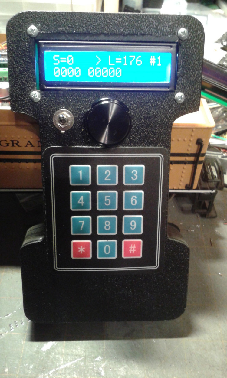
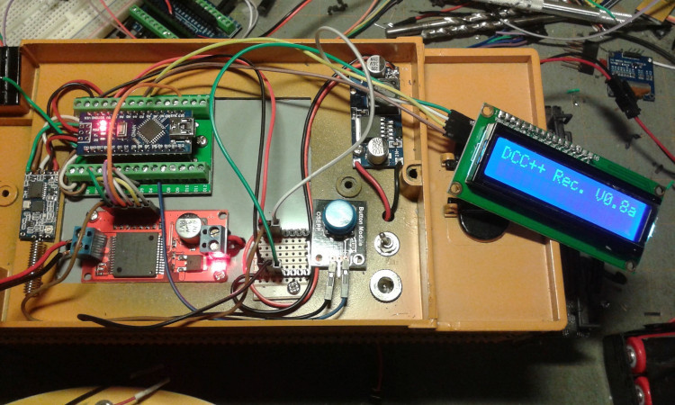
Right is the prototype Throttle made from layers of 1/4" PVC material (Sintra) and 1/8" thick ABS plastic. Above is the prototype layout of the receiver and Motor controller before the custom PCB boards were made.
I wanted to try to make an inexpensive wireless DCC system to operate trains on my garden railroad to supplement my Aristocraft 10 Channel Train Engineer system and RailBoss Hobby system and use lower cost 14.8V Li-Ion Battery Packs that I build, which the Aristocraft Train Engineer is incapable of using due to the voltage it requires. I did some research and saw that the Dave Bodnar had been experimenting with Arduino's and various Motor Driver boards to make a wireless cheap DCC++ system that fit my needs but was designed for track side use and still required a DCC decoder.
The system was simple, required few components and was inexpensive (approx $50.00) and it had additional functions that the Aristocraft Train Engineer didn't have. These functions would allow me to add sound as well as constant lighting to the engine.
I downloaded all the schematics and Ardunio code from Dave's website and then started gathering up all the parts listed on his schematics. Some of the parts I already had and some I needed to order. I found that if I ordered the Arduino Nano's and the DFPlayer MP3 modules and the Motor Controller module off Ebay and waited a week or so I could buy the at a much lower cost than if I purchased them locally. I used the time waiting for the parts to arrive to design a custom circuit board that would fit in both the tender and function as the receiver and in the throttle as the transmitter.
The beauty of Dave's design is that it uses the HC-12 transceiver module in both the Throttle and the Engine. No special software was needed other then using a downloaded app to change the Baud rate from 4800 to 15200. That's all that was required.
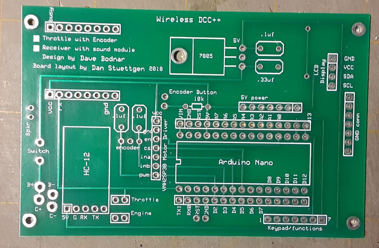
The board I designed is laid out in such a way that you only install the parts needed. If its going to be Throttle just add those parts and like wise for the Receiver in the Tender add only those parts needed. Both boards will have common parts such as the Arduino Nano , the HC-12 and the 7805 voltage regulator and its 2 capacitors.
After I had designed the board. I laid out all the parts to make sure that the all fit without any interference with other parts. Once I had a good layout and triple checked the wiring, I uploaded the file to ExpressPCB to have them made. It was $51 to have 5 board made and silk-screened. That's enough for 1 throttle and 4 receivers or 2 throttles and 3 receivers.
Items used in this system: (makes one wireless Throttle and one receiver) Most parts were purchased on ebay or through Mouser electronics
Arduino Nano (2) .
HC-12 Tranceiver (2) .
LM7805 5V regulator (2).
14.8V 4 Cell Li-Ion Battery pack or up to 20V. (1)
9V Battery (1) Duracell recommended for long life
Miniature DPDT toggle switch. (2)
Miniature SPST toggle switch . (2)
Miniature Momentary push button switch (1)
2x16 serial back light LCD display for Arduino (1)
DFPlayer MP3 module (1) Optional about
.1uf Caps (6)
.33uf Caps (2)
Rotary Encoder (1)
10K resistor (1)
3x4 Membrane adhesive Back Keypad (1)
7 pin headers for wires with plugs to fit over .1" spacing (3)
4 pin headers for wires with plugs to fit over .1" spacing (1)
15 pin headers for wires with plugs to fit over .1" spacing (2)
5 pin SIP socket (2)
2 pin headers for Jumpers (1)
2 pin jumper (1)
8 pin SIP sockets (2)
30 pin IC socket (2)
VNH2SP30 Motor Driver Module (1) Sparkfun
Two 2 pin locking connectors - Male and Female ends - Aristocraft style to connect battery to controller and charger
One 6 pin locking connectors - Male and Female ends - Aristocraft style to run to engine for motor and lighting
Misc: red/black awg 24 wire to run from board to switches (4 feet)
Misc: red/black awg 26 wire for lighting (5 feet)
Breadboard jumpers with female connectors on both ends (10)
Plastic case for throttle (1) PacTec model TT-9VB/2AA $14.54
Plastic case for throttle (1) PacTec model TT-9VB/2AA $14.54
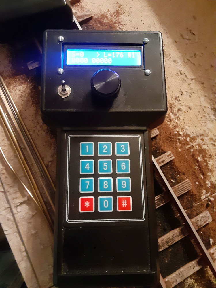
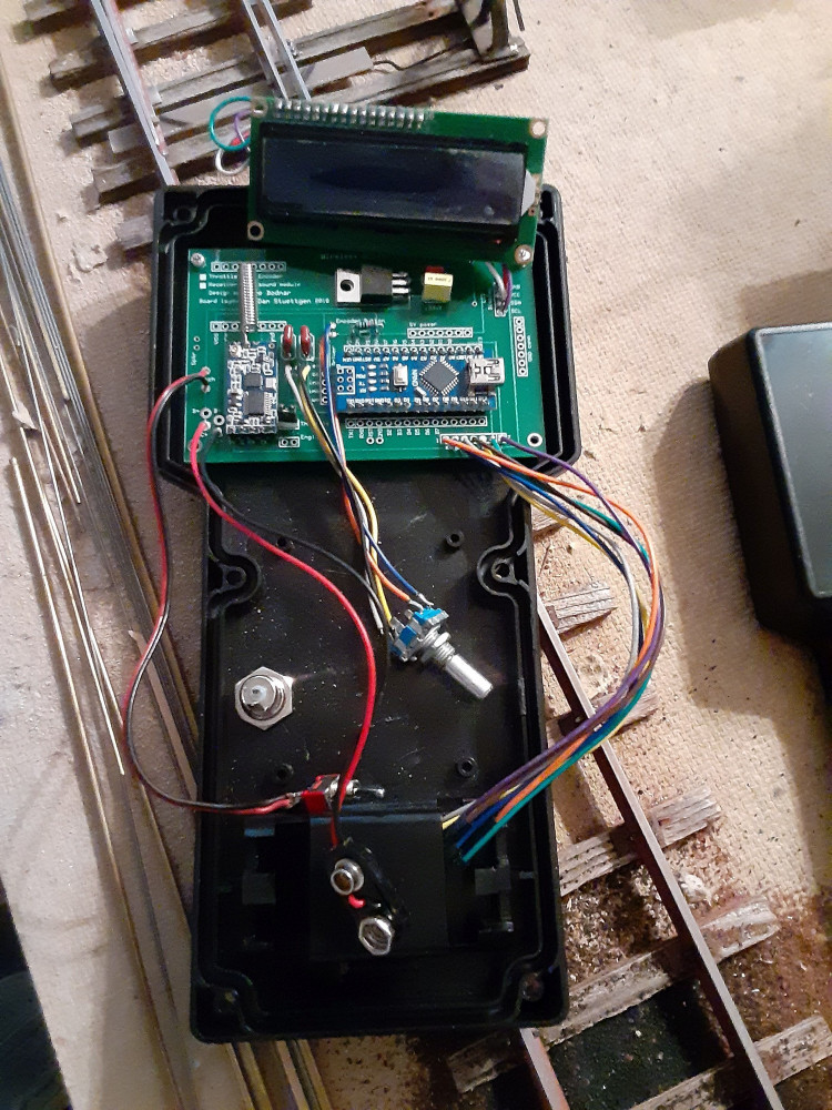
Left is the New throttle made using a commercially available case from Pac Tec. The Custom PCB was made to fit this case so it would fit the existing PCB mounting locations. Right shows the placement of the board with all the connections. I used a dremel to cut out the opening in the top of the case for the LCD display.
Top is the LCD display with wires soldered to the PCB. Lower right are the wires soldered to the PCB that go to the 3x4 membrane keypad. Next to that are the wires soldered to the PCB and to the Rotary Encoder. 2 caps and 1 resistor are needed for the rotary encoder. Next to those wires is the HC-12 transceiver that just plugs in to a 5 pin header. Next to the HC-12 is the wires for the 9V battery connector and the power switch.
Top is the LCD display with wires soldered to the PCB. Lower right are the wires soldered to the PCB that go to the 3x4 membrane keypad. Next to that are the wires soldered to the PCB and to the Rotary Encoder. 2 caps and 1 resistor are needed for the rotary encoder. Next to those wires is the HC-12 transceiver that just plugs in to a 5 pin header. Next to the HC-12 is the wires for the 9V battery connector and the power switch.
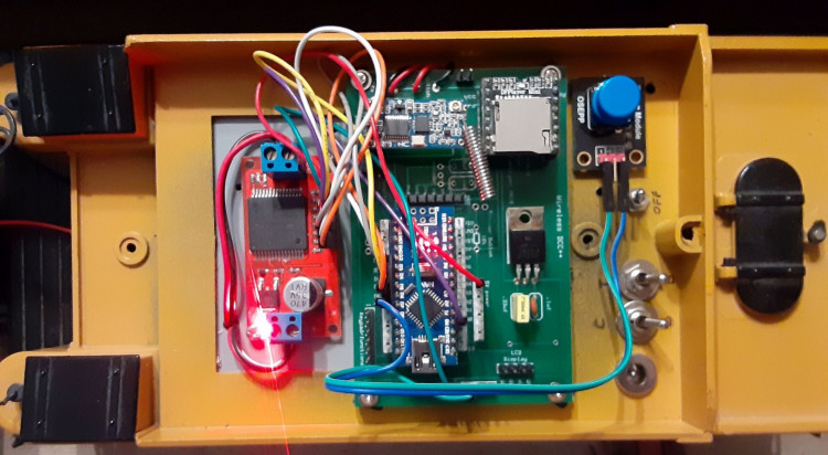
Above is the layout of the Receiver in a Bachmann Big Hauler Tender. Top right is the Binding Button that needs to be pressed when turning on the Receiver using the switch right below it. Throttle must already be turned on and set to the locomotive number that will be operated. Below the power switch is the Track / Battery switch for selecting either battery power or track power. If track power is used, the track power should be set to max power. Below the Track/Battery switch is the Charge/Run switch used to charge the battery without having to remove it by using the charge jack below the switch.
Center is the mounted PCB with the Arduino Nano and HC-12 transceiver and DFplayer MP3 Module in the upper right corner of the PCB. Next to it is the HC-12 transceiver and below that is the Arduino Nano. The Blue and green wires connect to the Binding button. The red and black wires at the top of the board are the Power switch and 9V battery wires. The mass of colored wires go from the Ardunio Nano to the VNH2SP30 Motor Driver Module. The red and black wires going to this board go to the Lith-ion Battery pack and the Track/Battery switch
Center is the mounted PCB with the Arduino Nano and HC-12 transceiver and DFplayer MP3 Module in the upper right corner of the PCB. Next to it is the HC-12 transceiver and below that is the Arduino Nano. The Blue and green wires connect to the Binding button. The red and black wires at the top of the board are the Power switch and 9V battery wires. The mass of colored wires go from the Ardunio Nano to the VNH2SP30 Motor Driver Module. The red and black wires going to this board go to the Lith-ion Battery pack and the Track/Battery switch
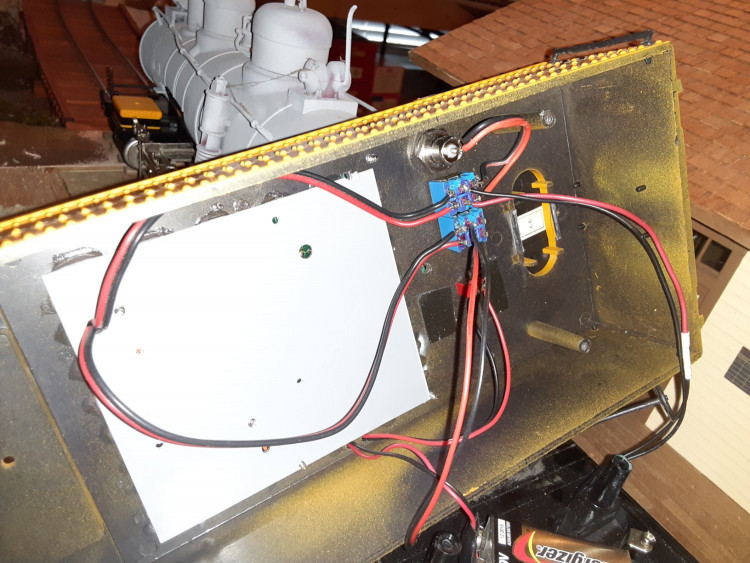
Top is the charge connector wired to one side of a DPDT switch. Center contacts are wired to the Lith-Ion battery pack. Other side of the switch go to the power terminals on the Motor Controller. ( top left black and red wire) Bottom left Black and red wire comes from the output of the motor controller to the left side of the second DPDT switch. The center contacts of this switch go to the motor. The right side contacts would go to the wipers on the axles in the locomotive to receive track power. Below this switch is the SPST power switch to turn on the receiver board. The 9V battery that powers the receiver board is seen at the bottom.
I have not tested the sound capabilities of this system yet, but I have tested the outputs for lighting. Connections D10 - D13 are for the lights, Headlight , Cab lights and Classification LED's. A 320 ohm resistor needs to be soldered to the Positive side of the LED and then its wires soldered to these connections on the board. the negative side of the LED's can be connected together and then one wire connected to one of the ground pads or use individual grounds for each LED.
A jumper needs to be used to let the board know if it is to be used as Throttle or as a receiver . After the two pin headers are installed, put the jumper across the two pins.
As mentioned before this board is used for both the Throttle and receiver. Just install the parts that are needed for its particular use. Receiver will not use the LCD connections or the keypad connections or the encoder parts. Like wise the Throttle will not use the DFPlayer Mp3 module.
Both Throttle and receiver will use the Arduino Nano, the HC-12 as well as the 5V regulator and its caps.
The Arduino code that is on Dave's website works as it is and works well. As I dont know how to program in C++. I have not made any changes, but I think some enhancements to then code would be nice to have. One would be to find a way to hard code the receiver /engine ID into the program before it is uploaded to the receivers Ardunio nano to be able to eliminate the binding button. This would allow you to have multiple engines already powered up and then just selecting the engine number of the throttle, your ready to go. As designed, you could not park an engine inside an engine house and be able to pull it out with the throttle as you would need to bind it to the Throttle by pushing the button as you power it up.
I would also like to see code added that would automatically play the sounds of the whistle when the engine moves forward and reverse in accordance with prototype practices.
One other enhancement would be to change the code to be able to use a 4 line LCD display as the case that I am using is designed to accept a larger 4 line LCD display. This would allow for additional information to be displayed, to better list the function buttons.
Maybe someone out there that knows how to code in C++ might like to tackle both of these enhancements. The main one is to eliminate the Binding button and hard code the engine number when uploading the code to the receiver Arduino Nano.
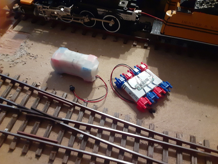
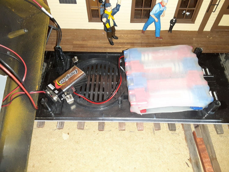
Photos above show the types of Battery Parks I make and use and the placement of the batteries in the tender. There is enough room inside the tender for a 4 cell 14.4 battery pack and a 9V battery and plenty of space left over to add a speaker for the sound module.
I hope that this will inspire others to build this Wireless DCC++ system as an alternative to the High Priced control systems available for the guys that want to run Dead Rail for your garden railroads or indoor layouts. I plan on using mine on my indoor layout along with my Easy DCC system made by CVP Products. If anyone would like to use the board that I designed here, I can send you the layout file and you can upload it to ExpressPCB to have them made. You will have to download their software first, but its free to use. I have considered having a number of board made for sale as well, but until I get any interest on that, I will hold off.
I feel that this is a cheap alternative to the systems on the market for guys that want to make there own. For about $100 you can build 1 throttle and 4 receivers. That includes the plastic case and all electronic parts and switches. Batteries would be extra. you can use which ever suppliers you like for the batteries, but I make my own. ( yeah I have read over and over again, to never build you own battery packs. but I have been building them cheaply for 8 years with no issues what so ever. As long as you use a BMS board and follow the instructions that come with them and pay attention to what your doing and using 18650 cell holders. Its easy and very reliable and cheap to make. about $12.00 for a 14.4V 3amp pack. )
I feel that this is a cheap alternative to the systems on the market for guys that want to make there own. For about $100 you can build 1 throttle and 4 receivers. That includes the plastic case and all electronic parts and switches. Batteries would be extra. you can use which ever suppliers you like for the batteries, but I make my own. ( yeah I have read over and over again, to never build you own battery packs. but I have been building them cheaply for 8 years with no issues what so ever. As long as you use a BMS board and follow the instructions that come with them and pay attention to what your doing and using 18650 cell holders. Its easy and very reliable and cheap to make. about $12.00 for a 14.4V 3amp pack. )
My Home made Wireless DCC++ system in operation on my Fn3 Layout under construction.