Brass G scale Switch Stand Tutorial
Scratch Building an operating G Scale Switch Stand
by
Dan Stuettgen
Before I start with the detailed step-by-step directions on how to build the operating switch stand, you will nee the following materials. I purchased all of these materials at my local Ace Hardware store and in 1-foot lengths. I
Materials needed:
#8 brass washers (1 for each switch stand you plan on building.)
5/32” brass tube K&S Engineering stock number #128.
3/32” x 1/16” brass rectangle tube K&S Engineering stock number #262.
1/2” x 3/32” solid brass stock. K&S Engineering stock number #241.
1/8” brass tube K&S Engineering stock number #127.
1/4” x 3/16” solid brass stock. McMaster Carr stock number 8954K903
1/16” brass rod. K&S Engineering stock number #162
.010 brass sheet K&S Engineering stock number #251
I wanted to use operating switch stands on my garden railroad in areas that are within reach as I think they really add a lot of interest to the track layout. I researched a number of manufacturers that had them available, but they were either not suited to outdoor use or they made out of a white metal and easily bent or were to expensive for the number I was going to need. So doing some more research I found a number of photos to use as reference for the one I wanted to build and also came across an article on building a switch stand out of plastruct that looked like the one I was going to build, but the plastic ones would not worked to operate the turnouts. They were meant to be connected to turnouts with switch machines and would move when the turnout was electrically thrown.
.
 1. I stated off my making a crude jig out of a 5” x 7” x 1/4" piece of wood and drilled a 5/32” diameter hole somewhere near a corner about 3/4” in from the edge.
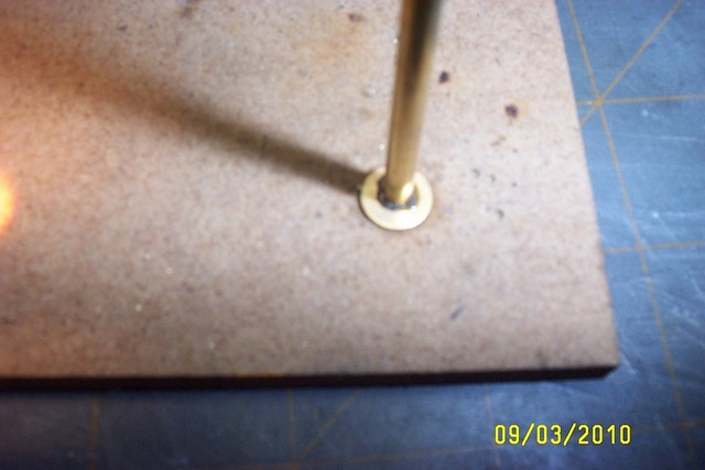 2. Insert the 5/32” brass tube in to the hole. (I used K&S Engineering Brass stock #128) Next slide a #8 brass washer down over the tube so it is flat against the wood jig, and then solder the washer to the brass tube.
 .
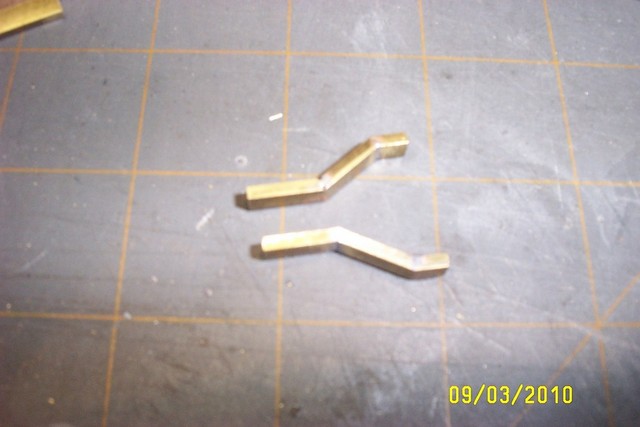
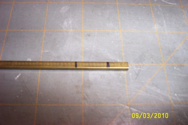 3. Mark a 3/32” x 1/16” brass rectangle tube (K&S Engineering stock number #262) 1/2” and 1 1/4”from the end, then flip over and mark the opposite side 1” from the end. These will be the cut marks for bending the legs for the switch stand. When making the cut, only cut half way through the rectangle tubing at the 1/2” and 1” marks. Do not cut the 1 1/4” mark until after the leg has been bent and soldered at the bend locations.
 4. Bend the brass rectangle so that when it is placed on the jig to be soldered that the first section is 1/4” higher than the last section. I used a 1/4” piece of Sintra to hold the first section at the right height while I soldered the second cut. I used a chunk of brass as a weight to hold it down while I soldered it cut. A trick I did to make sure I had a good solder joint, was to stuff some solder inside the tube at the bend of the brass rectangle so when I soldered the cut joint that it soldered the inside while I soldered the outside, making a nice strong joint.
 .
 5. After soldering that bend in the rectangle leg, flip the piece over and solder the other cut joint in the same manor. After soldering the second joint, cut the brass rectangle away at the 1 1/4” mark. This will complete one of the legs of the switch stand. Make the second leg in the same manor as the first one.
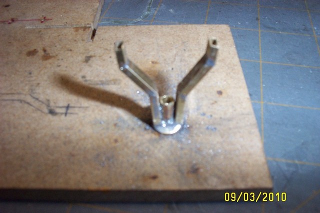 6. Insert the 3/32” brass tube with washer attached back into the hole in the wood jig with the washer flat against the wood. Solder the 1/2” end of one of the legs to the brass tube with the end of the rectangle tube pressed against the brass washer. After soldering the first leg to the brass tube, cut the tube off leaving 3/8” sticking up next to the tube. Solder the second leg to the brass tube in the same manor on the opposite side of the tube marking sure that both legs are parallel. File and clean solder joints as needed.
 .
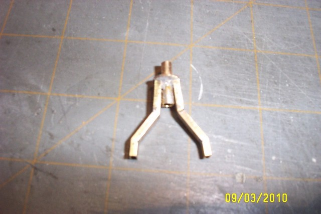 7. Assembly should look like this after legs have been soldered in place.
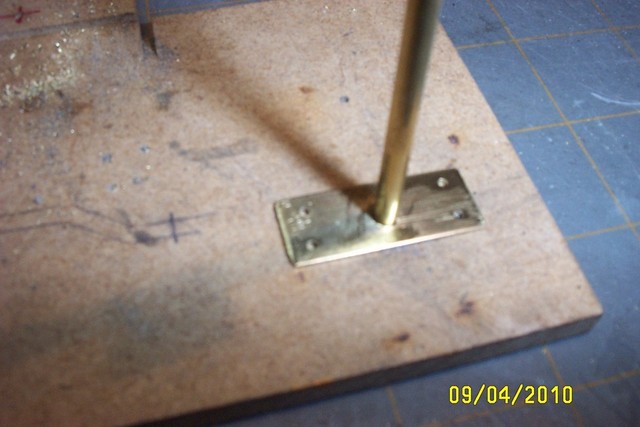 8. Cut a piece of ½” x 3/32” brass stock 1 ¼” long. (K&S Engineering stock number #241) This will be the base of the switch stand. Draw a line from corner to corner diagonally forming an X in the center of the piece of brass. Drill a 5/32” diameter hole at the mark. Also drill 4 holes 1/8” from the edges at the corners for the mounting spikes or screws. Drill whatever size hole you will need for your mounting method. I used Micro Engineering 1/2” spikes to mount mine, but you can use small screws if you like. Using a spring loaded dimplier make it easy to find the mark to drill the holes and keep the drill from wondering while you are drilling the holes. Insert the 5/32” tubing through the hole in the plate and in to the wood jig and solder. After soldering cut the tube off 1/8” above the plate and 1/16” below the plate.
 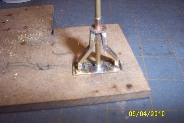 9. Insert a 1/8” diameter tube (K&S Engineering stock number #127) into the tube of the base section with the 1/8” section of the tube in the base point upwards. Now slide the leg section down over the 1/8” tube till the legs touch the base plate. This will hold the leg section upright while you solder the legs to the base section. When soldering is complete, clean up the solder joints off the base of the switch stand.
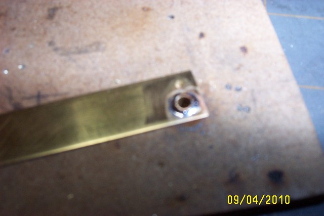 10. Drill a 5/32” hole and 1/16” hole in the end of the 1/2” x 3/32” Brass stock. Solder the small cut off piece from the 5/32” brass tube from the switch stand base into the 5/32” hole. Then cut this piece 3/8” from the end of the brass stock. File the tube so the it is 1/16” above the surface of the brass stock, now insert a 1/8” brass tube into the 5/32” tube so it is flush with the end and solder. This will form the switch stand linkage to the turnout. Cut the 1/8” tube 1 3/4” long after soldering.
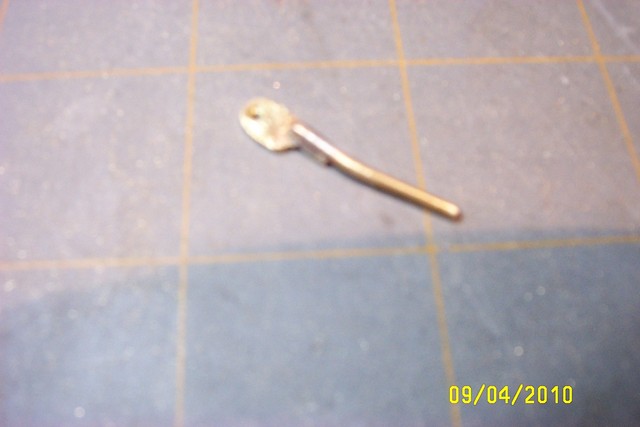
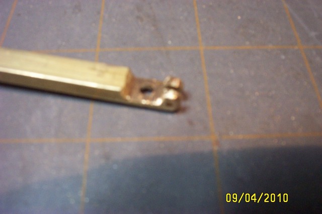 11. Use a piece of 1/4” x 3/16” solid brass stock and drill a 1/8” hole 5/16” from the end on the 1/4” side of the brass stock. Drill a 1/16” hole 3/32” from the end of the brass stock on the 5/16” side. Using a Dremel cut off wheel, cut a slot in the end of the brass stock the width of the cut off wheel, but make the cut about 3/16” long. Be sure to the cut slot in the center of the 1/4” side of the brass stock.
 Now use a file to remove the brass material after the slot to 7 /16” from the end of the brass stock on the 1/4” side until the brass stock is only 1/16” thick you should have something that resembles an L shape with a slot cut in the thick part or leg of the “L”. Cut this part at the 7/16” mark from the brass stock. This will be the handle and pivot assembly. If you wear glasses, you will notice that this looks a lot like the hinge part of the glasses.
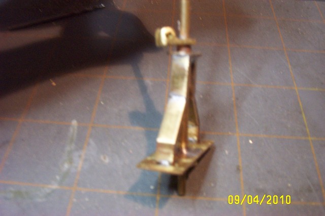 12. With the switch linkage inserted into the switch stand, slide the handle pivot assembly down onto the 1/8” tube. Align the linkage arm to be 90 degrees from the handle hinge and solder to the 1/8” tube.
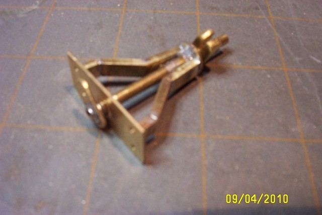
 13. Your switch stand now should look like the above photo. Cut a piece of 1/2” x 3/32” brass stock and drill a 1/16” hole approx 3/32” from the two corner edges. Cut this piece off the brass stock 1/4” from the end. File the corners round on the end where the hole is drilled. Now solder a 1/16” brass rod to one edge of this piece on the end away from the rounded corners and hole. Make a slight bend in the rod 1/4” from the edge of the brass plate, then cut the brass rod 1/2” past the bend. File the excess brass away from the brass plate next to the brass rod only. It should look like the photos below
 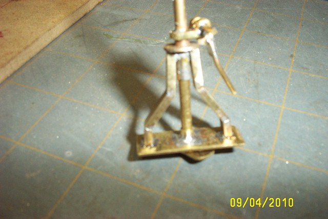 14. Insert the arm into the slot in the pivot assembly with the bent part of the arm away from the switch stand. Slide a 1/16” brass rod through the hole in the side of the pivot assembly and through the hole in the arm and then through the other side of the pivot assembly. Solder the brass rod to the outside of the pivot assembly and cut rod off. Then file both ends of the rod flush with the edge of the pivot assembly.
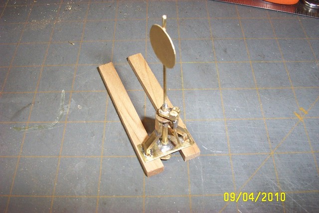 15. Cut a circle 3/4” diameter out of .010 brass sheet stock ( K&S Engineering stock number #251). I used a pair of scissors and kept cutting the corners off until it look pretty close to being round and then used a file to finish rounding it. Solder a 1/16” brass rod to the target circle with 1/4” past the end of the circle, and then cut the rod to 2 1/2” long. You might like a different style of target, so make one that suits your needs in the same manor.
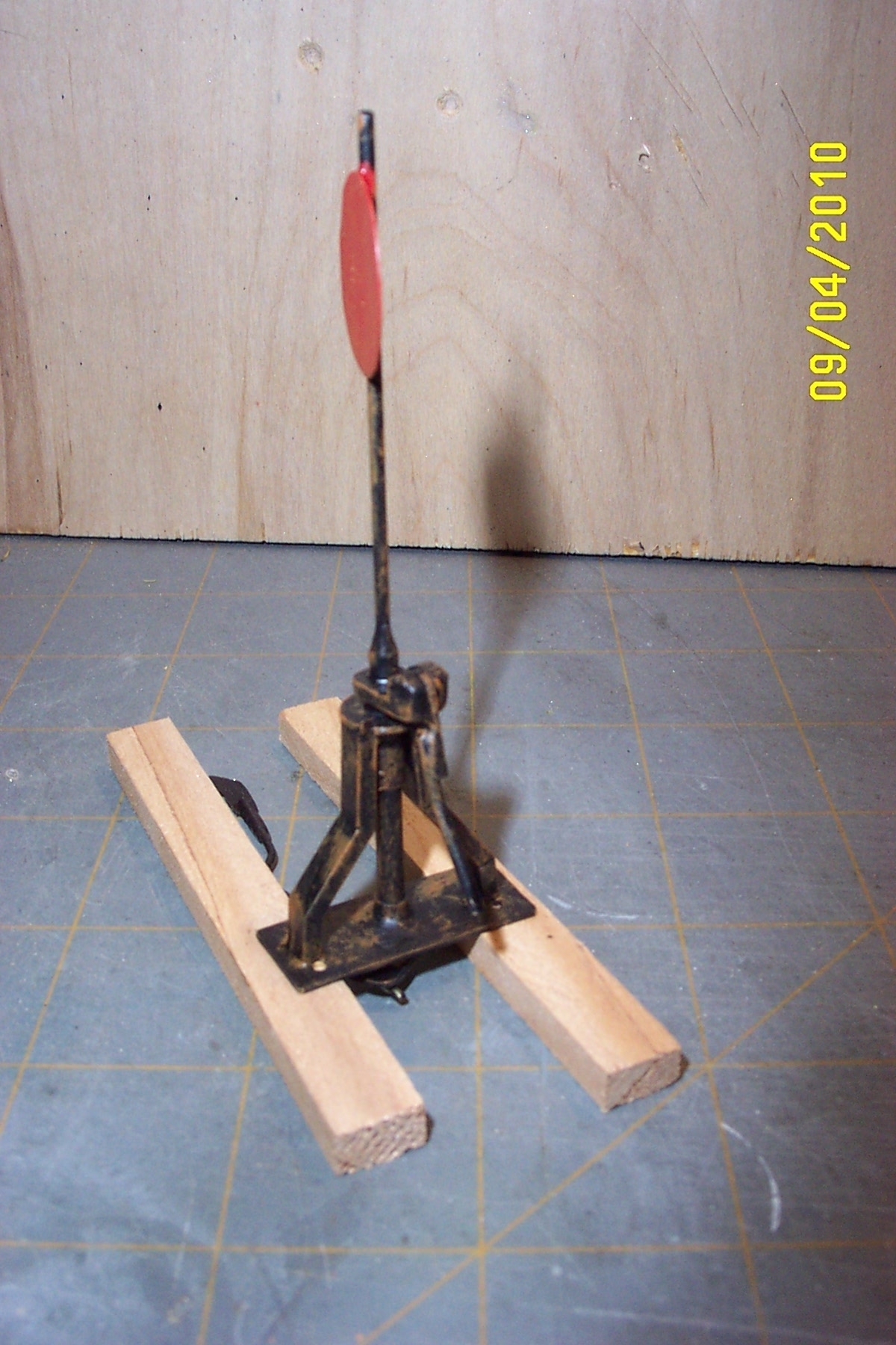
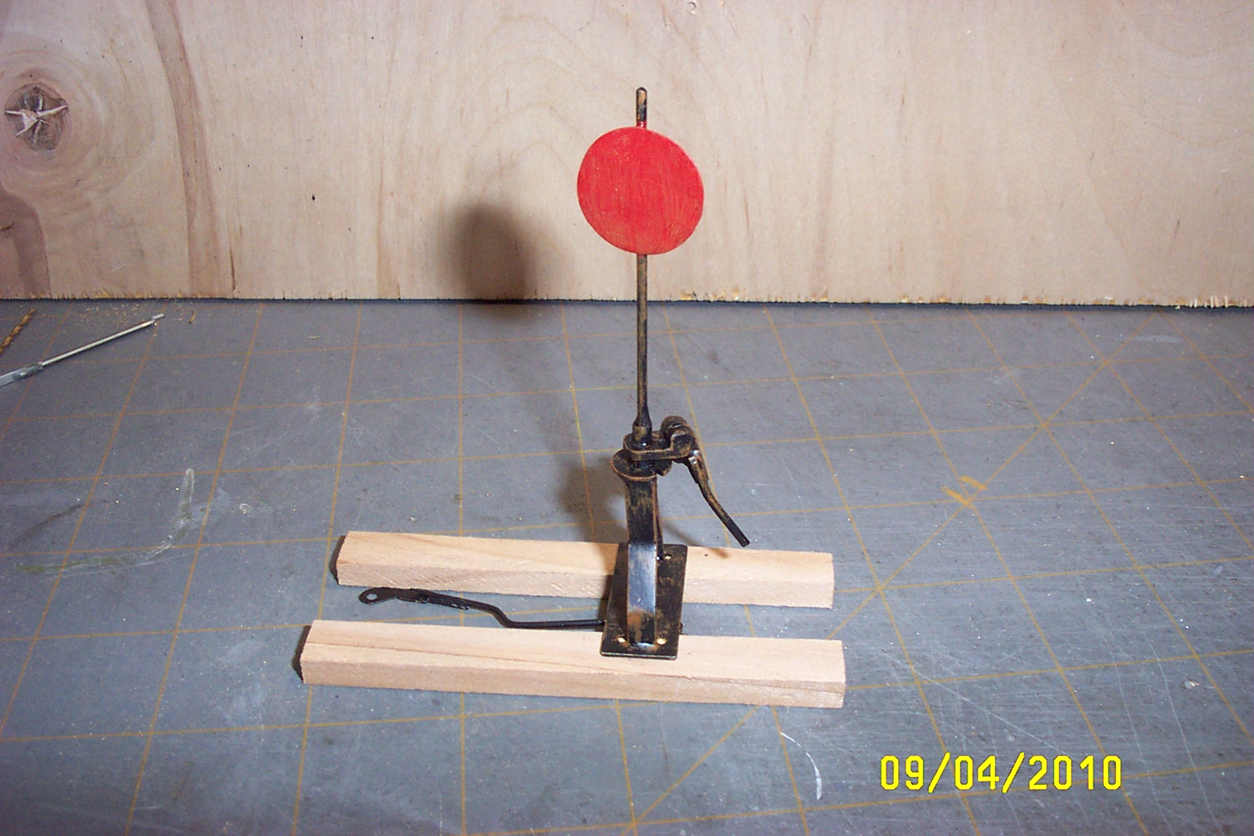
 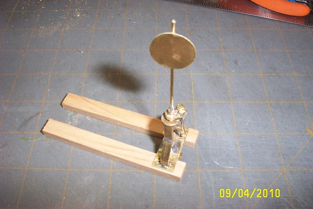 16. Make two notches in the brass washer next to each leg on one side of the switch stand. The arm will lock into these notches to keep the points of the turnout from moving. Slip the 1/16” brass rod soldered to the target into the hole on the top of the switch stand and solder in place so that the target is parallel with the track when the switch is set for straight through. Target would be perpendicular to the track when thrown for the siding. Your switch stand is now complete. Paint as desired. Make linkage to go from the switch stand to the turnout out of 1/32” piano wire. I use this switch stand to operate my hand made #5 turnouts that are made out of code 332 Steel rail and it works like a charm.
.