75MHz Rail Boss Controller Tutorial
This Tutorial in my attempt to use my existing 75Mhz Ground Frequency Transmitter and Receivers with G Scale Graphics Rail Boss Plus train controller.
by
Dan Stuettgen
Before I start with the detailed step-by-step directions on how to assemble the control system , you will need the following items.
Items used in this system:
Futaba SkySport 4 radio transmitter - 75.990 Mhz Channel 90 .
Futaba FP-R127DF radio receiver - 75.990 Mhz Channel 90 .
"G" Scale Graphics Rail Boss Plus (Hobby) Controller.
14.8V 4 Cell Li-Ion Battery pack .
Miniature SPST toggle switch.
Voice Recording Module 2 x 20sec sections - Product # A96020
9V Battery & Battery Connector
LM7805 Voltage regulator
Yellow LED
Red LED
Several 2 pin connectors with wires attached that fit over .1" spacing headers
Two 2 pin locking connectors - Male and Female ends - Aristocraft style to connect battery to controller and charger
One 4 pin locking connectors - Male and Female ends - Aristocraft style to run to engine for motor and lighting
I wanted to try using my existing 75Mhz R/C equipment to operate trains on my garden railroad to suppliment my Aristocraft 10 Channel Train Engineer system and to be able to use lower cost 14.8V Li-Ion Battery Packs that I have built, which the Aristocraft Train Engineer is incapable of using due to the voltage requirements it requires. I did some research and saw that the Rail Boss Plus fit my needs and is was not all that expensive ($89.00) and it had additional functions that the Aristocraft Train Engineer didn't have. These functions would allow me to add sound as well as constant lighting to the engine.
I contacted "G" Scale graphics and asked if I could use the rail Boss Plus with my existing 75Mhz equipment instead of the 2.4Ghz radios that they recommend since the input to the controller is standard RC servo signals. I was told that it should work with no problems, so I purchased a Rail Boss Pus controller and was very pleased with the service and speed at which I received the product.
.
 The engine that I selected to install the Rail Boss Plus controller in was one of my Bachmann 4-6-0's that had been sitting on the self waiting to to be converted to Battery operation. After dis-assembling the tender , I did a placement test on the various components to se if they would all fit. First thing I did was to remove the bachmann sound system, but left the speaker. I had to cut away the mounting stud for the sound system in order for the LI-Ion battery pack to sit flat on the tender floor. I also had to cut away the 9V battery holder at the rear of the tender to make room for the RC receiver.
 The white wires going around the tender shell mounting posts is the RC receiver antenna. It is wrapped around the posts 1 1/2 times and the tied in a knot.
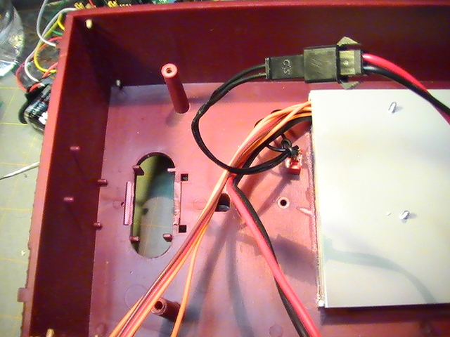 I removed the Plastic Coal load to create access to the rail boss from the top of the tender. Using Styrene strips and sheeting, I created a shallow box for the rail Boss Plus to sit it as well as the sound module leaning an acess hole to route the wiring through going to the power switch , battery and RC Receiver.
 At this time I installed the SPST switch to connect the LI-Ion Battery pack to the Rail Boss Controller. You can see it right next to the grey styrene plate that the rail Boss Controller will sit on the opposite
side
.
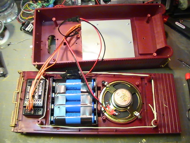
 Here you can see the placement of the Rail Boss Plus controller and right above it is the dual 20 second sound module from Electronics 123. One of the sounds is a bell that was recorded of the internet of a bell on a C-16 locomotive. The other sound is a whistle sound also recorded off the internet of a whistle on a K-28. Although these are not the correct sound for the 4-6-0, I liked how they sounded.
 The red and black wire running down to the orange RC wires is the wires running to the speaker. The Red and Black wires going to the white connector goes to a motor to bench test the controller while I wait on some more Aristocraft style mating connectors. The other Red and Black wire running off to the top of the photo go to the 9V battey board to power the sound module. You can see the on/off power switch mounted in the tender shell.
The two LED's are for testing the system, but will eventually go to the headlight and cab lighting LED's
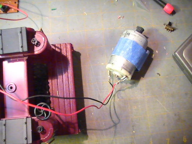 This is the 12V Johnson Motor that I am using to test the Rail Boss Controller system while I get everything wired up and operational. It will be removed and Aristorcraft style mating connectors and wires will be added to run to the motor in the Engine
 This is a simple power board I made to power the sound module. It uses a LM7805 Voltage regulator powered by a 9V battery. the board also contains a on off switch and a LED and resistor. This board is being reduced in size so it can be added next to the sound module over the top of the white and green wires. A second SPST switch will also be added to the tender shell on the other side of the coal load mounting hole to activate the sound system. labeling will also be added and the 9V battery will be housed inside the tender.
.